.: MMI LED Swap
This was originally brought up on Audizine forum after someone stumbled across a picture of an MMI unit from an A6. The owner had gone and swapped out the LED's of certain buttons so they matched the screen. For those with the MMI High units such as the 2G and 3G you'll understand what I'm talking about if you go look at your screen colours.
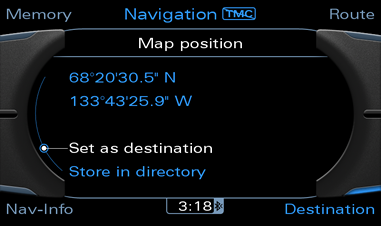
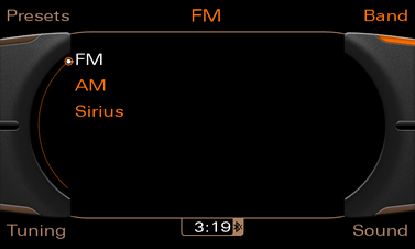
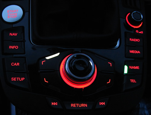
Essentially when you switch the Radio or Media you have an orange screen and when you got to Telephone you have green and finally NAV is blue. Using those as a guide I have changed out the main red indicator lights of the matching buttons to the corresponding colours of the screen.
This is not a mod for just anyone to jump into. If your not skilled in using a soldering iron or own a hot air station you could cause damage to your main board. Now at $700 for a replacement you want to be sure of what your doing. Now keeping that in mind this really isn't a hard job just one that takes a bit of patients and working knowledge of soldering.
After I did my LED's I finally broke down and bought a hot air station from eBay. It's been a few years since I checked and was amazed at the pricing of these units. They start at $40 and go up from there. The unit I purchased cost $125 with free shipping, included a soldering iron and a ton of free tips and spare heater elements. Now if your going to try this and your new to the soldering world this is your best bet. The heat range is low enough that your not going to hurt anything unless you really try and it will make this mod a breeze. If you go this route doa quick search on the internet and watch a few videos you'll see how easy they are to use.
Difficulty rating.. Well if your experienced with soldering or have a hot air station I would say 2-3 out of 10 for the soldering and the same for removing the MMI unit from your car.
LED choices are subjective but I'll list what I used here. I would have liked to have found some slightly brighter orange lights but I'm still happy with what I have used. I will not be giving a full electronics course here so try and take what you can from this but don't sweat the details to much.
The actual operating currents of the Red LED's are 1.95volts and 20ma. Chances of finding those exact voltages for LED's are slim. Different colours seem to require different voltages. Not to worry the MMI will output the power required for these LED's just don't go crazy on your choices. Keep the operating voltages below 5v and you should be fine. Getting LED's that work at 20ma is fairly easy. I tried a few different LED's in the different colours to choose the ones I have now but feel free to experiment. I ordered all of my LED's from DigiKey. They shipped quick and their pricing was good. Just be careful if your ordering from there. They list the same LED's in more than one configuration. Some LED's are sold as single and others as strips or reels. They are all the same but you will pay a feel for anything other than singles so just double check your parts so your not paying an additional fee for the wrong selection.
Ok I lied, lets go over some LED basics. I am no expert and I apologize if I get some information wrong. Please contact me if you see anything that needs correcting.
Your going to see some numbers and letters when looking at LED's so I'll try and give you an idea of what your looking at.
First of all there are different package types for LED's, these are basically the shape and form of them. The package type used for our regular LED's are 2-PLCC, don't get tempted to buy something that looks like them but use a different package.
Colour. When your looking at LED's although they will normally tell you the colour you can see variations of the colour in a number that ends in NM. NM is the rating of the wave length of light. Different wave lengths emit different colours. If your interested in looking at the ranges for each colour check out wikipedia's site here. Here are the ratings for the ones I used:
Blue: 470NM
Orange: 606NM
Green: 528 NM
The last item you care about is the brightness of the LED. These are usually measure in mcd (millicandela). This is way to complicated to get into here. As one with a lower number may be brighter than a higher depending on it's emitting angle. For the purposes of this article lets assume higher is brighter. Now certain colours are hard to find in a higher output but still seem to perform well. If I had my choice I will keep everything over 200mcd but some are lower and still look good.
Ok so that should give you enough knowledge to go shopping for your own. Bet your wishing I would get to the mod by now.....
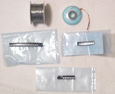
Supplies:
Solder: I like it as thin and small as I can get it. Your not doing plumbing here. Most solder come in a 60/40 marking (60% tin and 40% lead) although this is fine it's not the best. This type of solder can cause unstable joints if disturbed during it's cooling stage back to a solid. The best mixture to use if you can find it is 63/37. Don't worry I used 60/40 for most of my life without much issue but since I know now I always go the other route. Now lead solder is not allowed in Europe anymore so your looking for a solder with a high tin low copper combination. Solder melts at about 220 degrees Celsius so don't over do the heat.
Solder wick (DeSolder Braid): Although you shouldn't need it have some on hand. If you go a bit to heavy on the solder this is used between the board and your iron to absorb solder when it's in a meted state. Basically you place it on top of the solder you want to remove then put your iron on it to heat up the solder below and suck it up.
LED's again. Use at your discretion. I chose to change out the red LED's around the dial to white. You may want to skip those or do something different. I chose diffused lower light white LED's as I didn't want them to bright in the dark. I'm considering changing them to yellow now for something different. LED's are cheap so order lots of spares incase you do a future project or mess one up. You'll want to make sure you have spares in the future.
All are using Digikey part numbers:
2 x Blue - 475-2723-1-ND
2 x Green - 475-2685-1-ND
2 x Orange - 475-1131-1-ND
4 x White - 475-1138-1-ND (Optional)
Solder: SMDSW.20 40Z-ND
DeSolder Braid: 473-1061-ND

Tools For MMI Soldering:
Soldering Iron (preferable adjustable) or Hot Air Rework Station
Tweezers
Small flat head screwdriver
T10 torx screwdriver
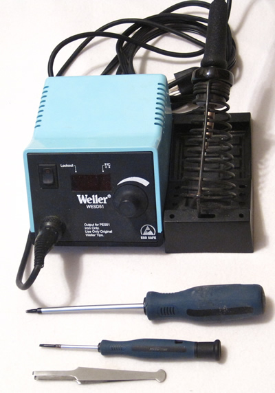
Tools for MMI Removal:
Small tool with hooked end to pull out AC controller
Small flat head screwdriver
Trim removal tool or similar tool

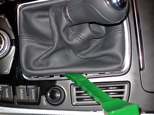
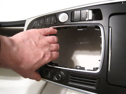
The first step is to get the MMI controls out of the Vehicle. I will vary from the Bentley manual to make this easier for you to do this on your own and lower the risk of scratching any trim.
Start by releasing the shifter boot from the MMI controls. Although I have not performed this on an automatic the procedure is the same except put the transmission in the S position before you start with an automatic.
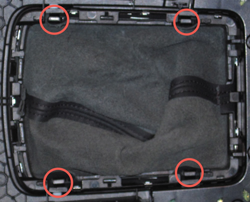
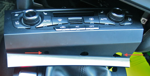
There are 4 clips holding the bottom of the boot to the MMI controls. The boot is tight and the clips just clip over the bottom of the controls to hold it in place. Your going to take your trim tool or equivalent and just pry the boot up and out on each side.
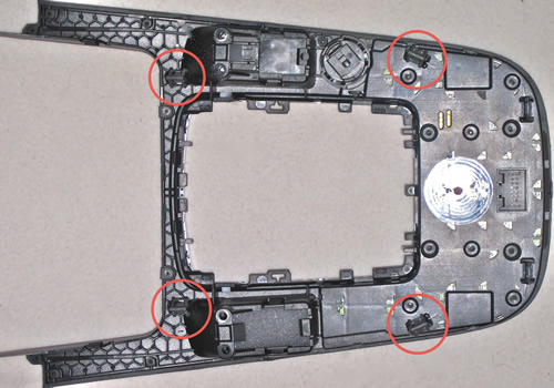
Here you can see the 4 clips you are releasing.
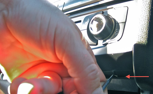
Pulling out the AC Controller. This is easier with a spare set of hands to hold it when you have it removed but you can do this procedure fairly easy on your own.
The AC controller has 3 holes on the bottom of it. Take a your hook tool and place it one of the holes on the end and pull. It will pull out a bit then alternate to the other hole and pull (alternate until you have the unit pulled out). It holds in place with 4 pressure clips so it's not hard to pull out.
I apologize for the pictures but this should give you more than enough to remove the unit. I used a larger tool than what's shown. I simply used this one as an example.
Here you can see the holes in the bottom of the unit:
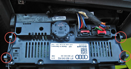
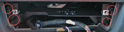
Here are the 4 clips that hold the unit in place:
And the dash where they clip in:
Once the AC unit is out put your hand under the back of the MMI controls and pull up. This will pull the clips out of the consol. I always work with a quick and positive motion when I work with clips to prevent any undue stress to the unit. Do not pull up to far as there are a number of plugs to be undone and the one for the push start if equipped is fairly short.
Here you can see the 4 clips that hold the unit in place
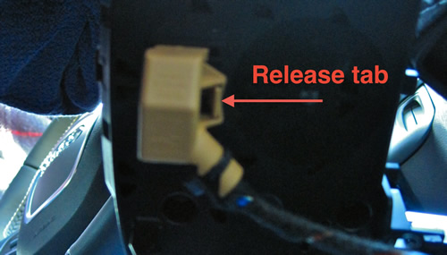
It helps to use a small screwdriver to push the release tabs down for the plugs. They will slide right out once the tabs are depressed.
The first plug you should release is the Start/Stop button. This harness is shorter than the others so you have to release it first which will allow you more room to work on the others.
Start Stop Button
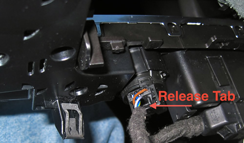
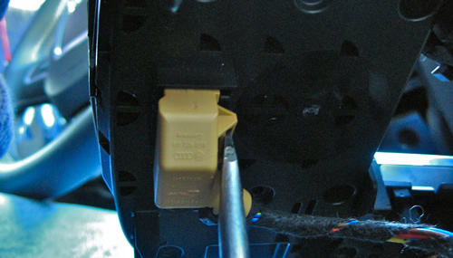
Slide a small screw driver in to depress the tab and just pull on the harness. That is the easiest way to release them.
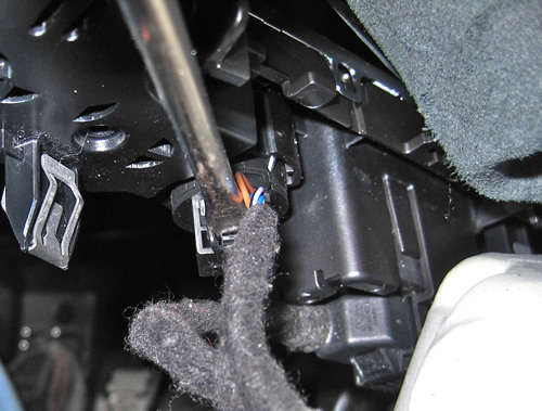
The MMI Plug
Release in the same manor:
Now if you are going to need to use the car prior to completing this mod you need to do a few things. Remove the emergency brake button and plug it back in and make sure you leave your MMI selected to radio so you have something to listen to. Other than that you can use the key in the dash if you have push start to start the car and you can drive without the controls in the car without any risk of problems.
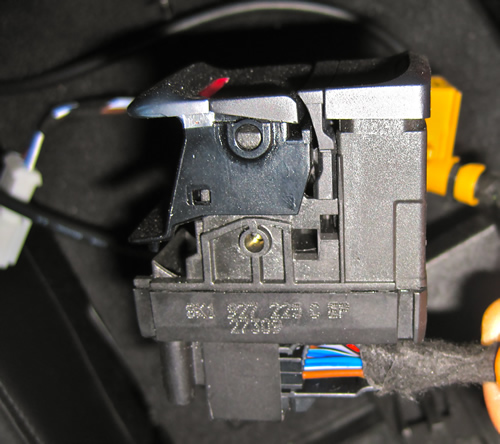
To remove the emergency brake button release the harness in the same manor then unscrew the two screws that hold the button in. You then release the clip on each side of the button and push it down to remove it from the MMI surround. If your going to do the install in one shot then don't worry about removing the button. This is only if your planning on driving the car while your MMI is being worked on.
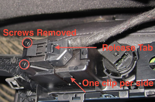
Here is the button plugged back in for use while the car is being worked on. Just a quick note. The brake will hold while the button is out so if your not moving the car don't panic.
You can now remove the controls from the car.
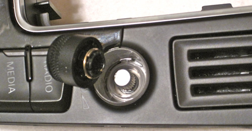
Our next step is to disassemble the MMI controls. Your first step is to remove the volume knob. It just pulls off so give it a good pull and take it off.
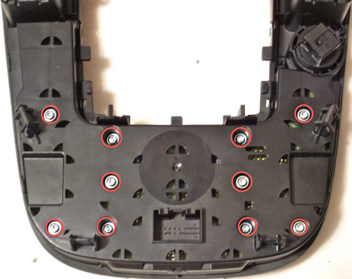
The next step is to remove the 10 T10 torx screws from the back of the unit.
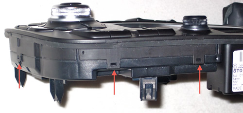
The last step is to release the clips around the unit. There is one clip that is hard to get to and you will need your small screwdriver for this. Release all the other clips first prying the unit up a bit so they don't reseat then move to the last one. As you release the last one pull up on the casing to expose the board.
There are a total of 6 clips holding the cover on, you can see the first 3 here. There are 2 on the opposite side and one hidden which I will show in a separate picture.
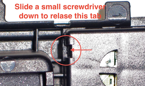
Here is the hidden clip. Do this one last.
The board will just pull out now with out any effort. Keep the top of the controls handy just in case you need to verify the LED's you are working on.
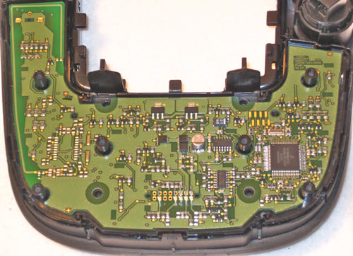
Here's a couple pictures to help you orient your colours.
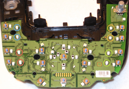
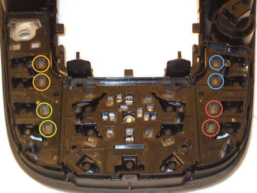
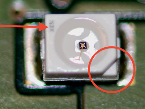
Note the direction of the LED's before you start. The new LED's have to go back in the same direction. You should see tiny writing on one side and a notch on the other to help orient the position.
Having an anti static mat to work on is ideal for this but use a place mat or something under the board to prevent static. Make sure you touch something metal before starting with the board to prevent static discharge. It gets very dry up here so it's an issue so just use common sense and safe practices. Don't go rubbing your socks on carpet and touch your board.. You know what I mean.
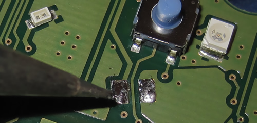
Work on one colour at time and put the red LED's away as you pull them so you don't confuse them with the new ones.
Warm up your Soldering iron or turn on your hot air station and start warming things up. Most components don't recommend soldering above 450 degrees Celsius if you can control your temperature. If you can't just be careful not to overheat an LED.
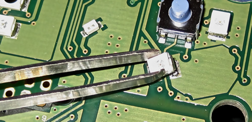
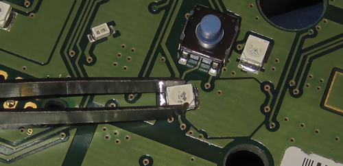
Now if your using hot air simply move the air back and forth from side to side until you can lift the LED off of the board with your tweezers.
*Since I only have 2 hands I had to prop the pictures. You would of course be holding your tweezers in one hand and the soldering iron in the other.
If your using a soldering iron heat one side of the LED and lift with a bit of pressure on that side until you feel the LED lift. Do not pull excessively. You don't want to rip it off the board until it's ready to lift or you could pull part of the trace. Once you have pulled the component up hold it while up with the tweezers until the solder cools then move to the other side and repeat. You may need to go back and forth one or two times to get the LED off completely. Don't rush it you don't want to harm the trace on the board.
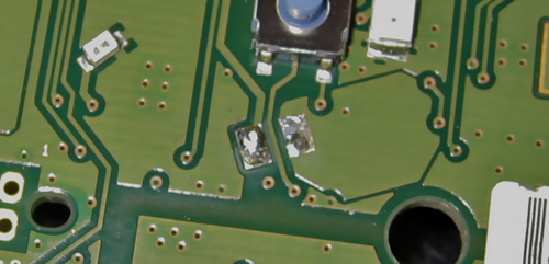
Now if you did pull some of the trace off not to worry just get your solder out and flow just a small amount back over the pad to replace the missing pad.
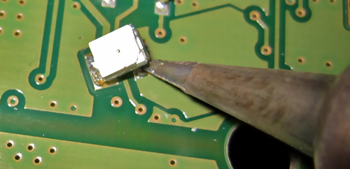
With the led removed take your soldering iron and heat the left behind solder and make it nice and smooth on the board. You shouldn't need to replace any back on the board if your lucky. You just need a thin layer to attach the new LED.
Once the solder is smooth get your new led and hold it in place with your tweezers and heat up one side of the solder. Once the solder heats up the LED should bond back to the board. Don't worry if it's not on exact. You can reheat the pad and move the LED around until it's in place.
Now this may seem like and odd technique but what I do now is put the tweezers down and put my finger on top of the led and push down as I heat the solder. This ensures the LED is seated all the way down. I then heat the opposite side while continuing pressure. I then repeat again on the original side. Just my method to ensure everything is seated properly. The entire process should take about 30 second once you get the hang of it.
Now repeat for the other LED's and reassemble in reverse.
Congratulations you now truly have a unique Mod. This of course isn't limited to the B8 and can be done on any MMI type controls. Feel free to play with colours and selections to your own tastes.


Please note: AudiEnthusiast.com is in no way associated to Audi or VW in any way shape or form. All brand names and manufacturers listed here are for informational purposes only and are in no way endorsed by AudiEnthusiasts.com unless stated other wise.
WARNING!! All modifications and changes are done at your own risk. This site in no way approves the modifications performed here for your vehicle. Please check with your dealer before performing any changes as they may void portions of your factory warranty.