.: Ambient Door Pocket Lighting
Using LED's for Pocket Lighting.
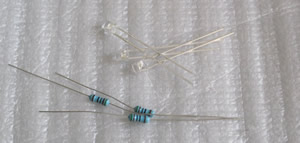
You'll need to pick out the LED's you'll want to use.
There are two methods for the LED's. You can put them together yourself or you can buy them pre made. Of course going pre made will make life easier. You can get LED holders but depending on how tight the holes are you can get away without them or use hot glue to fix them in place.
LED Parts:
8 x 3mm flat top red or white LED's.
8 x 1/4 watt resistors (you should buy LED's that come with them it makes life easier)
8 x 3mm LED holders (optional)
Sources:
Pre Wired 3mm LED's (saves soldering the resistors in after the fact like I am doing)
3mm LED Holders (This is an ebay link which may not last forever, so search for 3mm LED holder to find an alternative if this stops working)
Misc:
Solder
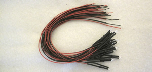
Shrink Wrap
20' small gauge wire (preferable 2 separate pieces 10' long in different colours)
Cloth Wrapping Tape
Glue or Epoxy (optional)
Tools:
Wire Cutters
Soldering Iron
Drill
13/64 Drill Bit (Depending on LED Holder)
Heat Gun (or similar device for shrinking heat shrink)
Before you can start you need to determine how you are going to wire your lights. There are a number of options. You can tap into the ambient lighting as described in the previous install. You can tap into just the dash lighting that is adjustable by the dial on the light switch or you can tap the dash light AND the door opening light to give you the closest effect to having the ambient light.
The cost of this project can get fairly high with all the connectors and wires needed to make this plug and play if you want to tap into both sources. I'd recommend that if your using the route of LED's you may want to just splice into the source wires.
For access to dash lighting you can tap into the lighting wire that comes from the door lock or window switch. If your going to make a harness I would recommend the door lock so you can keep things simple since all the doors use the same plug.
If your set on making a plug in harness you will need the following plugs and wires:
8K0 973 754 x 4 (this is the plug that will go into the lock switch)
4E0 971 613 x 4 (this is the plug that would go into the existing plug)
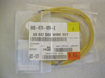
000 979 009 E x 8 (Wires for 8K0 973 754)
000 979 012 E x 8 (Wires for 4E0 971 613)
Now the above will allow you to tap into the door lock circuit (of course this assumes you have door locks)
Now if you want to tap into the door opening lights as well you will need even more plugs. The only thing this gives you is the lights going full brightness when the door opens.
893 971 632 x 4 (This is the plug that will go into the door light at the bottom of the door)
893 971 992 x 4 (This is the plug that would go to the existing light plug)

000 979 021 E x 4 (Wires for 893 971 632)
000 979 103 E x 4 (Wires for 893 971 992)
Now the purpose of the pass through harnesses is to allow you to tap into the factory wiring without altering your factory wiring. I would strongly suggest you consider your options on this. If your planning on making this permanent I would simply splice the wiring instead of going through the process of making these pass threw harnesses. It will make the installation faster and easier and lower your cost considerably. Of course the option is yours. If your choosing the pass threw route simply assemble the male and female connecters back to back is in pin 1 to 1, 2 to 2 and so forth.
The harness will just plug in between the factory plug and it's device such as the door lock or light.
To see this type of install in action just look at the LED cup holder for a perfect example of a tapping harness. LED Cup Holder
No once you have the wiring type you want to do figured out here is the wires you will need to attach to I am providing the main plug plug number and you can trace them back to which ever switch you are going to use for the source:
Wire that controls switch brightness
- Front: (T32 / Pin 4, blue/brown)
- Rear: (T16 / Pin 2, blue/brown)
Wire that controls door entry lights
- Front: (T32 / Pin 16, brown/yellow)
- Rear: (T16 / Pin 12, brown/yellow)
If your going to use just one source such as the switch then you can move onto making your harness. If you are going to use both sources you need to look at the following diagram and collect a few more parts.
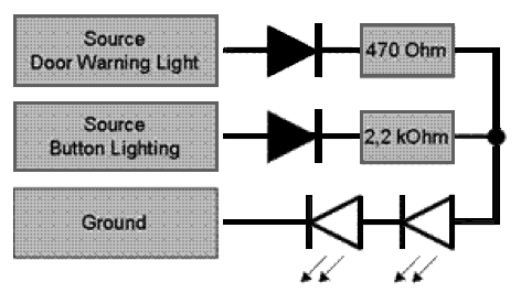
If your going to go with the method above you'll have to buy some diodes. For those that aren't electronically savey. A diode prevents power from feeding back into a circuit. So in the example above when you open the car door power doesn't feed back through and light up the dash lights and visa versa. Diodes get installed so the power flows through one way and and not back through the other. So understand which way they will need to go:
![]() the electronic symbol is:
the electronic symbol is: ![]()
Power flows from the left to the right in the orientation shown. Think of the line on the diode as a block to stop the power. So when placing a diode in a circuit the line points away from it's power source.
Now for the electronics guru lets talk a bit about a more customized LED install:
If you are going to build your own LED's you'll want a wide angle (120 degrees), with a light output of approx 20.000 mcd. Within these specifications, it’s the angle that matters most - the wider the better. An angle somewhat like 20 degrees will give you a sharp bounded light spot that can be distracting while driving at night.
Although I show how to do a simple independent complied LED construction, in the installation below 2 LED's are used, wired in series with a 470 Ohm resistor.
Depending on the type of LED you use you can vary the value for the resistor to achieve the appropriate brightness.
Now if your LED's pre made your can skip this next section on LED construction. If not your next step will be to assemble your LED's.
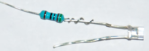
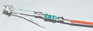
Start with soldering on the resistors.The resistor goes on the power side of the LED. On the LED's I was using that would be the side that had the longer lead and the non flat side of the LED.
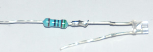
Next step was to solder on the wire then cover it with shrink tubing.
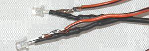
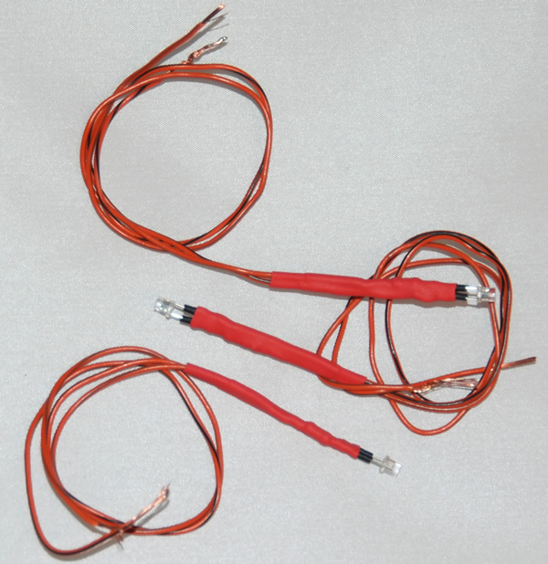
Repeat the procedure on the ground side but of course with out the resistor. When I was done I put one more piece of shrink tubing around the entire assembly for a little extra support.
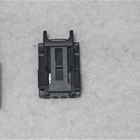
Very important step. In order to join your LED wiring to the door you will need to install some sort of connector. You will need a make and female connector to go from the door and the trim panel. In order to save yourself some money I would recommend going to an Auto or electronic store to buy some 2 pin connectors as they don't have to be Audi specific to join the two sides together. Now if you insist on using Audi connectors you may want to choose the smaller connectors used for the factory lights. The parts you will need will be as follows:
4 x 4E0 972 575 (Male Connector)
4 x 8E0 972 623 (Female Connector)
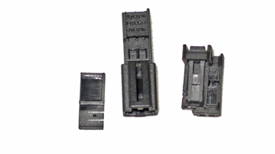
4 x 000 979 012 E (For Male Connectors)
4 x 000 979 009 E (For Female Connectors)
The next step is to start creating your final harness. Mock place the wires together then mark a joining point and connected all the wires together.
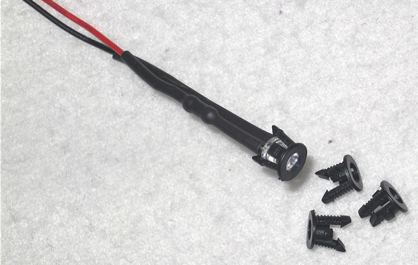
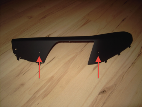
Drill a hole with a diameter of approx 3mm, so the LED holder (if you went that route) will just fit into it. Its a good idea to test drill and try the holder or LED in a test piece of material just to make sure you have the hole size.
Push the LED in the hole with its head flushed to the surface.
You can use a little glue to hold the LED in place but if the correct hole is used it should stay firm without it.
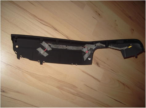
To secure the wires you can use some self-adhesive stripes of felt to prevent rattling and to fix wiring and LED's (not neat, but functional).
Here is a picture showing the holes drilled.
Here you can see the back side of the front handle. Keep in mind where the wiring will connect to the door side and route accordingly.
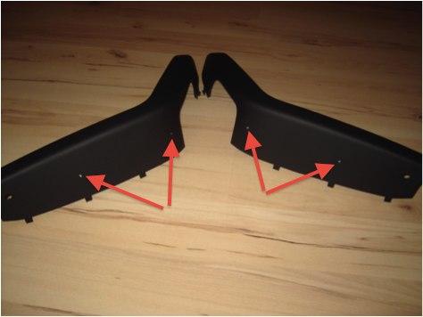
These are the back doors completed. Since the covers are symmetrical you may want to try and keep the holes in the exact same places.
Once the wiring is complete reinstall the door panel and connect the light.
Please note I did not do this type of installation on my car so I have tried my best to provide all the information you may need to complete it. I apologize if I have missed anything.
Please note: AudiEnthusiast.com is in no way associated to Audi or VW in any way shape or form. All brand names and manufacturers listed here are for informational purposes only and are in no way endorsed by AudiEnthusiasts.com unless stated other wise.
WARNING!! All modifications and changes are done at your own risk. This site in no way approves the modifications performed here for your vehicle. Please check with your dealer before performing any changes as they may void portions of your factory warranty.